Eiffel Tower: a shape calculated by the wind
The Eiffel Tower through a structural engineer’s eyes: a shape calculated by the wind
Everyone knows the Eiffel Tower. Fewer people know that its shape was not drawn by an architect – it was calculated from the wind. We have prepared a structural analysis of the tower based on public sources and on the original drawings that Gustave Eiffel published in 1900. We traced the origin of every figure, and where the sources disagree, we say so openly. Here is what matters from the point of view of a steel structures engineer.
The tower in numbers
Height: 300 m at the opening (1889), 330 m today including the antenna
Base footprint: 125 × 125 m
Material: puddled (wrought) iron, approx. 7,300 t
Parts / rivets: 18,038 parts, 2,500,000 rivets, not a single weld
Construction: 28 Jan 1887 – 31 Mar 1889, i.e. 2 years and 2 months
The idea did not come from Eiffel
In June 1884 the concept was brought forward by two of Eiffel’s employees: Maurice Koechlin, head of the design office, and Émile Nouguier, technical director. Their first sketch showed a 300-metre pylon made of four curved legs converging towards the top. In September 1884 Eiffel patented the solution and bought the rights from both of them.
Koechlin had studied in Zurich directly under Karl Culmann, the founder of graphic statics. This is not a historical curiosity but the key to the whole structure: the tower was designed with a method in which the result of the calculation is a drawing. The architect Stephen Sauvestre later added the masonry bases and the large arches between the legs. Those arches, however, are purely decorative – they carry nothing.

A shape calculated by the wind
The shape of the legs is not an aesthetic decision. Eiffel and Koechlin based the design on a simple condition: at every height, the wind moment must be balanced by the self-weight so that no tension develops in the corner chords. Higher up, the exposed area and the lever arm are smaller; lower down, the moment grows – which is why the legs spread apart towards the ground.
Eiffel’s own calculation sheets prove it. On Plate XXXIII of the monograph, the tower is divided into sections, and for each of them the wind bending moment and shear force are evaluated graphically. Forces were measured with a ruler on the force polygon and converted using the scale (“2 mm pour 10 000 kgr”). Directly from the scan we read two wind hypotheses:
- 1st hypothesis: 300 kg/m² over the full height (≈ 2.94 kPa)
- 2nd hypothesis: 400 kg/m² at the top and 200 kg/m² at the bottom

The second hypothesis introduces pressure increasing with height. This is the same idea that EN 1991-1-4 expresses today through the exposure factor ce(z) – a century before the standard existed.
How high did Eiffel aim? A pressure of 2.94 kPa corresponds to a wind speed of roughly 69 m/s (≈ 250 km/h). For a rough comparison: with a basic wind velocity of 24 m/s and terrain category III to IV, EN 1991-1-4 gives a peak velocity pressure at 200 m (the limit of the standard’s scope) in the order of 1.3 – 1.5 kPa. Eiffel’s value is therefore roughly double. This is our own illustrative calculation, not a figure from the sources, and the comparison is not one-to-one: we do not know to which area and with which force coefficient Eiffel applied the pressure.
Reality proved him right. The design amplitude of the top was 70 cm; the measured values are five to eight times smaller – typically up to 9 cm, and 13 cm during windstorm Lothar in December 1999 (wind speed 240 km/h).
Material: why iron, and why 18,038 small parts
The tower is not made of steel but of puddled wrought iron. In 1887 this was a material that bridge builders knew in detail, including its behaviour in riveted joints. Its modulus of elasticity (≈ 193 GPa) is close to modern steel, but its yield strength (≈ 160 – 220 MPa) is noticeably below S235. The material is softer and more ductile.
More important is how it was produced. A puddling furnace handled 360 to 410 kg per charge, and the material had to be removed by hand. Large sections simply could not be made from it – so the tower is assembled from 18,038 small parts into lattice members, and those again into lattice legs. The lattice is not ornament. It is a direct consequence of the metallurgical technology of its time.

Foundations: two solutions on one site
The four legs do not stand on identical foundations – and rightly so. The geology decided. The two piers on the École Militaire side sit on 2 m thick concrete slabs in sandy gravel above the groundwater table. The two piers next to the Seine had to go below the water level: steel caissons of 15 × 6 m with compressed air were sunk to a depth of 22 m.
The concrete carries hard limestone blocks with anchor bolts of 10 cm diameter and 7.5 to 7.8 m length (the sources differ), topped by a cast-iron shoe. According to the engineers’ calculation of the time, the pressure on the concrete foundation was only 0.49 – 0.53 MPa.

Erection: how four legs met with millimetre accuracy
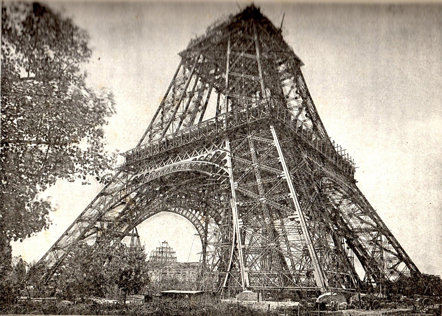
Up to the first platform, each leg is an independent cantilever leaning inwards, standing only thanks to scaffolding. Only when they are connected at a height of 57 m does a single frame come into being. At that moment four independently erected structures must meet, and pre-drilled holes must line up. The positional tolerance of a rivet hole was 1 mm.
The solution was twofold. The legs were deliberately built steeper than their final position. The shoes contained hydraulic jacks with a capacity of 800 t, and the scaffolding carried sand boxes from which sand could be released in a controlled way. Each leg could thus be lowered smoothly until the joint fitted, and then permanently wedged.

The organisation of fabrication would hold up even today. Fifty engineers produced more than 5,300 drawings in two years; every part had its own drawing. Almost 60 % of the rivets were set in the Levallois-Perret workshop; finished 5-metre sections arrived on site, were first pulled together with erection bolts and only then replaced by hot rivets. One worker died during construction – an exceptional record for the time, owed to guardrails, movable gangways and safety nets.


The tower in service: temperature and paint
For a 300-metre iron structure without insulation, temperature cannot be neglected. The sunlit side expands more and the top leans away from the sun by up to 18 cm; the seasonal change in height is about 20 cm. The 18 cm figure is confirmed by two independent sources.
Corrosion protection is a permanent task: every 7 years, 60 tonnes of paint are applied, and the tower has been fully repainted at least 19 times. The paint comes in three shades – lighter at the top, darker at the bottom – so that the tower appears uniform in colour against the sky.
What we take from the Eiffel Tower into today’s practice
- The shape should follow a structural condition. For slender masts and towers we do the same today: we look for the outline at which the corner chord stays free of tension under self-weight plus wind. Only the tool has changed.
- Wind increases with height. Eiffel’s second hypothesis is a forerunner of the exposure factor in EN 1991-1-4.
- Material and fabrication dictate how a structure is divided. Then the capacity of a puddling furnace, today available rolled sections and maximum transport length.
- Erection tolerance is solved at the support. An adjustable bearing is still the right answer to the question of how to connect independently erected parts.
- Prefabrication and complete documentation. As many joints as possible in the workshop, finished blocks to site. Today we do it in Tekla; Eiffel did it with 5,300 drawings.
- Different foundations on one building are fine, as long as the subsoil – not a wish for uniformity – dictates them.
What we verified – and what we did not
We read the two wind hypotheses directly from the scan of Eiffel’s plate; the 800 t jack capacity is confirmed both by the plate and by an independent source; the numbers of parts and rivets agree across three sources. The frequently quoted claim that the tower’s outline is exactly the curve of wind moments comes from a scientific paper (Weidman & Pinelis, 2004) that we have not read in the original – so we present it only as a principle, not as a verified fact.
The sources differ, for example, on the weight of the iron (7,300 t vs. 7,000 t), the height at completion (300 m vs. 300.65 m) and the number of workers on site (120 to 300). Material tests taken directly from the tower’s structure are not publicly available; the iron properties given here are general material properties.
Sources
- G. Eiffel: La tour de trois cents mètres, Paris 1900, volume of plates (public domain), Wikimedia Commons
- Wikipedia EN – Eiffel Tower, Wikipedia FR – Tour Eiffel, Wrought iron
- Structurae – Eiffel Tower
- STRUCTURE magazine – The Eiffel Tower at 125 Years (2014)
- C. Fivet, D. Zastavni, J. Ochsendorf: What Maurice Koechlin’s scientific contribution tells about his life, 5th Int. Congress on Construction History, Chicago 2015
- Photographs and drawings: Wikimedia Commons, public domain and CC0. Data retrieved 17 Sep 2026.
Are you designing a steel structure where wind, erection or connection detailing is decisive? At BVK-PRO we cover steel structures from structural analysis to shop drawings. Get in touch.
Ing. Ádám Varga
Authorized Structural Engineer, Steel Structures Specialist
BVK-PRO, s.r.o.